This study demonstrates that fast non-destructive testing using X-ray fluorescence(XRF) and X-ray diffraction (XRD) has the sensitivity necessary to detect minor variations of consequence in parts and recovered powders used in near-net-shape production with Inconel 718.
Nickel-Iron super-alloys, such as Inconel, are well suited for use in hostile high-temperature environments that require good creep, corrosion, and thermal shock resistance. Such super-alloys are favored for hot sections in aircraft engines and other demanding applications. Near-net-shape processes, such as additive layer manufacturing (ALM) or hot/cold isostatic press (HIP/ CIP), are appealing because they can produce new and complex shapes that minimize weight while still providing mechanical integrity under hotter combustion conditions for improved fuel efficiency. Microstructural hardening mechanisms, such as solid solution strengthening or precipitation of intermetallic compounds, can also be engineered into the near-net-shape manufacturing process.
In order to minimize waste in additive manufacturing and powder metallurgy processes, it is good practice to reuse the excess powder left over after each build. The recovered powder is recycled back into the powder hopper, where it is mixed with as-received powder. As more parts are made and more recovered powder is added to the hopper, the ratio of virgin to recovered powder may change. The recovery and reuse of powder for high-value materials like Inconel 718 has both economic and environmental benefits, but it is only safe and appropriate if the parts made with the recovered powder are identical to the parts made with virgin powder.
Mechanical testing of parts, while the benchmark for integrity, is destructive and time-consuming. Only a few parts can be tested as representatives of the entire lot. In contrast, X-Ray Diffraction (XRD) and X-Ray Fluorescence (XRF) are fast non-destructive measurements that can be applied to both the powder and all parts. Problems in the recovered powder can be identified before it is recycled into the hopper; and every part can be quickly examined for consistent production.
Small variations can have dramatic consequences in parts made by additive manufacturing. The speed and non-destructive nature of XRD and XRF are attractive for process control; but they are only useful if they have the sensitivity to detect minor variations of consequence in the powders and the parts. In this study, the first, eight, and sixteenth parts from a batch of sixteen parts were analyzed. The as-received powder and the powder recovered after the eight and sixteenth builds was also analyzed. The purpose of the study was to determine if XRD and XRF have the sensitivity to detect the minor variations that lead to differences in the performance of the parts.
XRD data were collected with the automated Empyrean Series 3 diffractometer with MultiCore optics. Because Inconel 718 is an Fe-containing alloy, a Co anode X-ray tube was used to ensure the best possible grain statistics and peak-to-background ratio. The improved sensitivity of a Co anode tube compared to a Cu anode tube for this alloy allowed for better detection of minor phases. The energy discriminating performance of the PIXcel3D detector was used to filter fluoresced noise from the Cr content in the alloy.
An Epsilon 1 benchtop energy dispersive XRF was used for fluorescence analysis.
The elemental composition of the powder was consistent, as shown by XRF results in Table I. The recovered powder had the same composition as the as-received powder, indicating that recycling the powder did not shift the chemical composition of feedstock. This also confirmed that no contamination was picked up during processing.
| Element | Average Composition (%) | Nominal Composition of Inconel 718 (%) |
|---|---|---|
| Ni | 54.8 | 50-55 |
| Cr | 18.8 | 17-21 |
| Fe | 16.8 | 17 |
| Nb | 5.0 | 4.75-5.5 |
| Mo | 3.0 | 2.8-3.3 |
| Ti | 0.9 | 0.65-1.15 |
| Mn | 0.2 | <0.35 |
| Al | 0.2 | 0.2-0.8 |
| Si | 0.2 | <0.35 |
While the XRF result suggests consistency, XRD shows a variation in the phase composition of the powder and the parts. The γ phase in Inconel 718 is a face-centered cubic Ni-Cr-Fe solid-solution alloy. The γ’’ phase in Inconel is a body-centered tetragonal intermetallic that tends to be Nb and Mo rich, and is often written as (Nb,Mo)Ni3 even though the exact chemistry may be different. Precipitation of the γ’’ phase is encouraged because it hardens and strengthens the Inconel part.
High angle data, above 110 deg 2theta, is necessary to resolve γ and γ’’ phases. At lower angles, such as around the strongest diffraction peak ~51 deg 2theta, the γ and γ’’ peaks overlap too much to be individually resolved. At higher angles, the diffraction peak positions split enough to identify and quantify the amount of γ and γ’’ phases in the Inconel 718. Figure 1 shows the profile of γ and γ’’ phases that produce the observed diffraction peaks between 105 to 125 deg 2theta.
Trace phases of Fe2Ti and (Nb,Ti)C are often added to encourage the formation of γ’ and γ’’ intermetallic precipitate phases for hardening and strengthening. These trace phases are observed in the low angle diffraction data (30 to 70 deg 2theta), as shown in Figure 2.
Analysis of the XRD data from Inconel 718 reinforces the importance of collecting data over a large angular range when possible. Low angle data is necessary to observe trace phases, while high angle data is necessary to resolve γ and γ’’ phases.
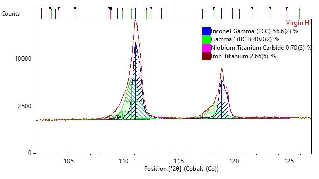
Figure 1. The observed diffraction data from as-received powder (red) is produced by combination of the diffraction profiles of γ (blue) and γ'' (green) diffraction peaks.
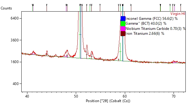
Figure 2. Identification of (Nb,Ti)C (pink) and Fe2Ti (maroon) trace phases in Inconel 718.
Figure 3 shows a comparison of high angle XRD data from powders and parts. This comparison reveals a variation in the broadening of the low angle side of the peak, which is created by the γ‘’ phase. While subtle, this peak profile clearly indicates that parts contain more γ’’ than the powder.
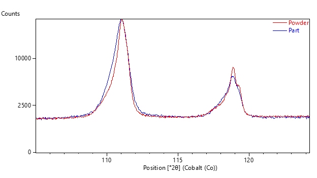
Figure 3. Comparison of XRD data from powders (red) and parts (blue), showing variation in diffraction profile created by differing amounts of γ''.
XRD data were quantified by whole pattern fitting, using the HighScore Plus software, to determine the amount of γ, γ’’, carbide, and Fe2Ti phases in each sample.
The powder contained, on average, 60 wt% γ and 37 wt% γ’’. Parts, however, contained more γ’’—37 wt% γ and 60 wt% γ’’. This is notable because Inconel 718 usually contains only 20% or less γ’’. At 60 wt%, the γ’’ content in the parts should no longer be considered a precipitate strengthening phase but rather the matrix phase.
As a reminder, XRD is a phase analysis tool and not a chemistry analysis tool. XRD can distinguish between the γ, γ ‘, and γ’’ phases found in Inconel, but it cannot determine the exact chemical composition of these phases. However, qualitative understanding of the probable chemistry can be extracted from the refined lattice parameters of the γ and γ’’ phases.
Table II compares the average lattice parameters of the major phases for the samples in this study and in published literature. In both powders and parts, the γ’’ phase has a larger c lattice parameter than typical. The larger lattice parameters in the γ’’ (and smaller lattice parameter in the γ phase) may suggest greater distribution of the large Nb and Mo atoms in the γ’’ phase. The elongated c-axis of the γ’’ phase also suggests more misfit with the γ phase, which is consistent with the conclusion that the γ’’ has exceeded the concentration of a precipitate hardening phase.
This study | Literature | |
|---|---|---|
γ: a (A) | 3.597 | 3.600 |
γ’’: a (A) | 3.602 | 3.596 |
c (A) | 7.250 | 7.218 |
The greatest phase variation was between powder and parts, but there was also variation within the powder and parts analyzed after the first, eight, and sixteenth build, as summarized in Table III.
Part 8 contained the least amount of the γ phase; correspondingly, the recovered powder had the largest amount of γ phase after build 8. By build 16, the ratio amount of γ and γ’’ was approximately equivalent to the virgin powder and the first part. This indicates that phase composition of the powder and parts was not consistent, and that the recycled powder sometimes had varying phase content.
Additional analyses are needed to determine if this variation is significant to the performance of the part, or if it would be considered “under control”. While phase analysis by XRD cannot validate the parts quality directly, these analyses show that it could be a useful near real-time monitor for process control after it is validated with mechanically testing.
| Sample ID | γ (fcc) [%] | γ ’’[%] | Fe 2 Ti [%] | Niobocarbide - NbC [%] | Rwp |
|---|---|---|---|---|---|
| Virgin Powder | 57 | 40 | 3 | 1 | - |
| After Build 8 | 63 | 35 | 2 | 1 | - |
| After Build 16 | 59 | 38 | 2 | 1 | - |
| Part 1 | 38 | 59 | 2 | 1 | 2.77 |
| Part 8 | 38 | 62 | 2 | 1 | 2.82 |
| Part 16 | 38 | 60 | 2 | 1 | 3.11 |
Other XRD analyses can also be used to predict parts performance, such as residual stress and texture analysis. The automated nature of the Empyrean Series 3 with MultiCore optics allows each part to be analyzed with iso-inclination residual stress and pole figure analyses after the powder analysis. Because the MultiCore system is fully motorized and automated, no user intervention is needed to collect the different measurements with optimized optics.
Iso-inclination stress analysis shows a variation in residual stress between parts, as summarized in Table IV. The residual stress in the phi=0 direction appears to correlate to the γ’’ content, though the variation is smaller than the precision of the measurement and therefore not necessarily significant. In the phi=90 direction, however, the stress varies significantly and correlates to build number and not to the powder composition.
These variations in residual stress are small and require high precision to measure. In this measurement, a high precision parallel plate collimator was used in front of the detector to provide the necessary data quality. Alternative geometries, such as 2D stress analysis, lack the precision to consistently measure this small variation.
Sample ID | Residual Stress (MPa) | |
|---|---|---|
Phi=0° | Phi=90° | |
Build 1 | 326 ± 25 | 90 ± 12 |
Build 8 | 312 ± 27 | 134 ± 21 |
Build 16 | 338 ± 18 | 169 ± 13 |
Texture analysis shows slight variation between parts which may be below the threshold for significance. Part 8, with the most γ’’ content, also had the strongest <200> fiber texture. Part 16 had the least <200> fiber texture. However, in all 3 samples the amount of texture was low.
Texture can be roughly quantified by the K-factor, which is the ratio of the intensity of the center of the pole figure (phi=0 chi=0) to the average intensity of the total pole figure. A larger K-factor indicates more intensity in the normal direction, and consequently preferred orientation of that crystallographic direction normal to the surface of the part. A K-factor of 1 indicates randomized texture in the normal direction. Table V summarizes the K-factor in three major directions for parts from build 1, 8, and 16. All parts have significant <200> texture and relatively random <111> texture in the normal direction.
| Sample ID | 111 | 200 | 220 |
|---|---|---|---|
Build 1 | 1.09 | 1.94 | 1.28 |
Build 8 | 0.99 | 1.99 | 1.23 |
Build 16 | 0.98 | 1.79 | 1.17 |
Use of recovered powder led to a slight variation in the phase content of parts; while the chemical composition was consistent. All parts contained an excess of γ’’ phase compared to conventional Inconel 718.
The most reliable monitoring of parts would incorporate both phase analysis and residual stress analysis. For this reason, all measurements were collected using the multipurpose automated Empyrean Series 3 diffractometer with MultiCore optics. All optics on this system are motorized and computer-controlled, allowing for dynamic reconfiguration of the system without user intervention. As an example, parts were analyzed using Bragg-Brentano divergent beam geometry for powder diffraction, line focus parallel-beam geometry for iso-inclination residual stress analysis, and pseudo-point focus parallel-beam geometry for pole figure (texture) analysis. The Empyrean Series 3 diffractometer with MultiCore optics can collect all 3 measurements from each part by automatically changing the optical configuration for each measurement. Powders could easily be introduced into the sample queue with the optimal configuration defined and automatically incorporated into their measurement.