This application note describes reflectivity measurements on non-ideal sample surfaces. It demonstrates the improvement of the reflectivity curves by the use of a beam knife in measurements on curved glass samples and shows the necessity of the beam knife to get accurate data from this kind of sample.
Grazing incidence X-ray reflectivity extends the area of analytical methods for thin layers. It allows the determination of many important characteristic parameters as layer thickness, interface roughness, layer density and interdiffusion effects between layers.
Grazing incidence X-ray reflectivity (GIXR) extends the area of analytical methods for thin layers. It allows the determination of many important characteristic parameters as layer thickness, interface roughness, layer density and interdiffusion effects between layers.
In this application note reflectivity measurements of curved glass surfaces and of oxidic layers on the samples are described. Due to some production processes the shape of glass surfaces is not perfectly flat but bent or undulating. These surface shapes may cause problems with the alignment of the sample and cause changes in the intensity near the critical angle in a reflectivity measurement. In these cases a beam knife to reduce the effective reflecting area of the sample might be necessary to perform a reflectivity measurement or to detect the critical angle with high accuracy.
In GIXR measurements the reflectivity of sample surfaces is measured around the critical angle. Below the critical angle of total reflection X-rays penetrate only a few nanometers into the sample, whereas above this angle the penetration depth increases rapidly. At every interface where the electron density changes a part of the X-ray beam is reflected. The interference of these partially reflected X-ray beams create the oscillations shown in reflectivity measurements. Therefore GIXR can be used to analyse sample surfaces and thin layers. Reflectivity measurements are a non- destructive tool to determine densities and thicknesses of layers on substrates and the roughness of external and internal interfaces. In general the determination of the critical angle θc gives the electron density and, with known stochiometric composition, the mass density of the reflecting medium. To determine this angle with high accuracy, experimental data of a well defined sample area have to be fitted with a simulation program. On curved samples this can only be reached using a beam knife.
This application note describes reflectivity measurements on non-ideal sample surfaces. It demonstrates the improvement of the reflectivity curves by the use of a beam knife in measurements on curved glass samples and shows the necessity of the beam knife to get accurate data from this kind of sample.
The reflectivity measurements were performed on an X’Pert3 MRD system. A programmable divergence slit (PDS) and an automatic beam attenuator were used at the incident beam side. On the diffracted beam side a programmable receiving slit (PRS) and a programmable anti-scatter slit (PASS) were used in a coupled mode. A curved diffracted beam monochromator limits the range of wavelengths entering the detector and reduces background radiation. A “De Wolff’s” beam knife was fitted onto the MRD cradle and adjusted in a position just above the sample surface to reduce the effective area on the sample for the reflectivity measurements.
Figure 1. Typical experimental set-up with beam knife
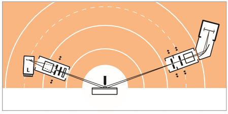
Figure 1 shows a typical experimental set-up used for reflectivity measurements with beam knife in our X’Pert3 MRD (Materials Research Diffractometer) system. A sealed tube with copper anode and long-fine focus (optical height 40 μm) was used. The generator setting was 40 kV/40 mA.
The programmable divergence slit (PDS) on the incident beam side was closed to a small opening, which allows an incident beam height of less than 0.04˚ in 2θ. On the incident beam side an automatic attenuator (Ni-foil) was used to increase the measurable dynamic range (7 - 8 decades). The typical background in this set-up is 0.2 - 0.5 cps. On the diffracted beam side a programmable receiving slit (PRS) and a programmable anti-scatter slit (PASS) were used in coupled mode.
Both slits were set to the same fixed opening (50-100 μm). A curved monochromator in front of the detector limits the detected wavelength range and reduces the background radiation. On both sides Soller slits (0.04 rad) were used to limit the axial divergence of the beam. The beam knife above the sample limits the effective reflecting sample area.
Whereas flat samples can be measured without a beam knife, measurements on curved samples might only be possible using it:
For reflectivity measurements an accurate adjustment of the sample according to the incident beam is very important. As a start, the alignment is performed with respect to the primary beam. For higher accuracy an additional alignment at one or more other
ω-angles of the sample (e.g. just below the critical angle or at a fringe position of the reflectivity curve) are necessary. The alignment should be done with an accuracy of approx. 0.001˚ in ω. Un-ideal and wavy sample surfaces cause changes in the rocking curve shape compared to flat surfaces. This prevents an accurate adjustment.
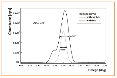
Figures 2 - 5 show rocking curves of a concave and a convex sample in the primary beam and of irregular shaped samples at an angle just below the critical angle, with and without a beam knife. They demonstrate that for an accurate alignment of a curved sample the beam knife is very desirable or even necessary. The rocking curves of bent samples (without beam knife) are often strongly broadened, deformed or sometimes there is not even a reasonable signal. In contrast the measurements with beam knife show small single peaks in the rocking curves enabling a good alignment. The tilt of the beam knife is adjusted parallel to the sample surface and the distance between beam knife and sample is adjusted in a way it cuts approximately 30% of the incident beam intensity.
Figure 2. Comparison of a rocking curve of a concave sample in the primary beam with and without beam knife
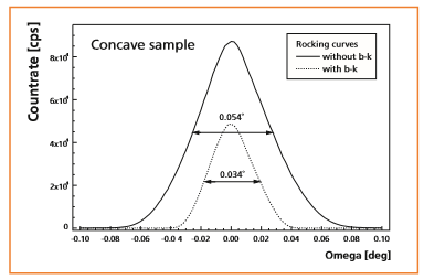
Figure 3. Comparison of a rocking curve of a convex sample in the primary beam with and without beam knife
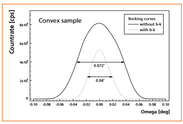
Figure 4. Comparison of a rocking curve, measured with and without beam knife below the critical angle (irregularly shaped sample)
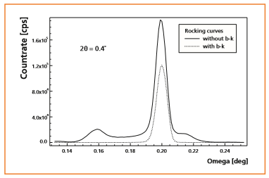
Figure 5. Comparison of a rocking curve, measured with and without beam knife below the critical angle (irregularly shaped sample)
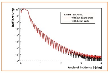
This example is supposed to show that a beam knife does not interfere with the quality of the data. Therefore a sample was chosen which could still be measured without beam knife. Figures 6 and 7 show the comparisons of reflectivity measurements of a Ta2O5 layer deposited on a slightly bent SiO2-substrate with and without a beam knife. The area around the critical angle and a larger angular range exhibiting fringes are displayed. The measurement time for both graphs were equal. Therefore the statistic is slightly different (lower intensity with beam knife).
The measurement shows that the beam knife improves the shape of the graph near the critical angle, whereas the shape of the curve above the critical angle is not noticeably changed. The improved shape (flat plateau) can be used for accurate normalization of the graph which is necessary for a good fit. Therefore the use of the beam knife allows the determination of the critical angle - and therewith the density of the reflecting material - with better accuracy. Small differences in the shape of the curve at higher θ-angles are due to the reduction of the diffuse scattering by use of the beam knife.
Figure 6. The area around the critical angle of a reflectivity measurement of a Ta2O5 layer on a bent SiO2 substrate with and without a beam knife
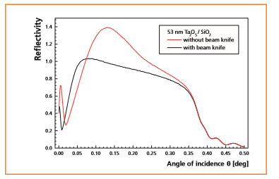
Figure 7. Reflectivity measurement of a Ta2O5 layer on a bent SiO2 substrate with and without a beam knife, plotted on a logarithmic scale
Curved sample surface shapes may cause problems with the alignment of the sample for reflectivity measurements. In such cases a beam knife that reduces the effective reflecting area of the sample might be necessary to perform a reflectivity measurement or to detect the critical angle with high accuracy.