
The performance of the Spraytec system can be verified by use of a standard photomask reticle. This is an optically flat glass slide upon which is deposited a series of chrome dots. When the reticle is placed in the Spraytec measurement zone, the reticle dots will produce a scattering pattern that can be analyzed by the system. By evaluating the particle size reported for this pattern, it is possible to check whether the Spraytec system is performing correctly.
This document describes the measurement procedure for Spraytec reticles with part numbers RTS2007 (RS3) or RTS2114. It requires the use of the Reticle Mount (EPC0060) which is supplied as part of the reticle kit. This mount allows the reticle to be mounted in the correct part of the Spraytec measurement zone.
|
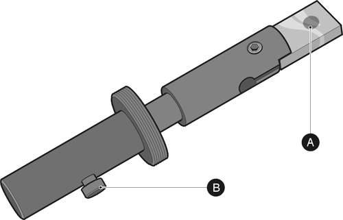
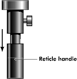
The Spraytec Reference Reticle, shown above, is used to verify the performance of the Spraytec system. The reticle holder contains a glass slide (A) upon which a pattern of chrome dots has been etched.
Once the reticle is attached to the Spraytec, the reticle pattern can then be entered and withdrawn from the measurement zone. The clamping screw (B) will keep the reticle glass in position during the measurement.
The results should match the specifications shown on the verification certificate supplied with the reticle. For reticle RTS2114, specifications are provided for the Dv10, Dv50 and Dv90 reported for the measurement of the reticle. For reticle RTS2007 (RS3) a specification is only provided for the measured Dv50.
If the verification certificate for the reticle cannot be found, please contact Malvern for a replacement certificate.
Reticle measurements follow the following procedure:
Before beginning any reticle measurements, the instrument must be prepared and checked to ensure that the measurement can be performed accurately. Perform the checks detailed below where applicable.
If the Spraytec has been set up to use a compressed air purge, this should be switched off during measurements.
Ensure that the instrument is correctly aligned prior to making a reticle measurement. This can be assessed by looking at the transmission signal (detector 0) reported during measurements. For a correctly aligned and clean system, the signal on this detector should be between 1200 and 2000 counts.
The instrument's optics should be cleaned prior to the reticle measurements. To assess the state of cleanliness a background measurement should be made. The background level should typically be less than 100 counts for each of the scattering detectors if the system is clean. A very clean system will show less than 50 counts on all of the active detectors.
The reticle glass should be cleaned and attached using the reticle mount.
If necessary, clean both sides of the glass, using non-silicone-impregnated lint-free lens tissue to wipe the surfaces. If there are oil or grease smears on the glass, use a glass-cleaning solvent such as ethanol.
The following describes how to insert the Reticle prior to beginning the measurement. Depending on the arrangement of the Spraytec, there are two methods of mounting the reticle in the measurement zone - one applies to an open bench Spraytec system, the other to the inhalation cell system.
Unscrew the black plastic shroud from the front of the bench-upright on the receiver side of the instrument.
Screw the reticle mount into the position that the shroud occupied. It should be mounted such that the port through which the reticle is then inserted is positioned horizontally and pointing towards the user.
|
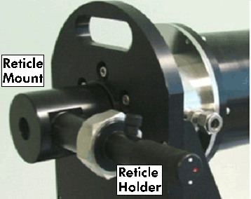
Screw the reticle holder into place within the reticle mount. It is important to ensure that the reticle dot pattern faces the receiver unit. The correct arrangement is shown below.
|
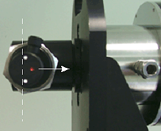
For reticle RTS2114 there are two white dots and one red dot on the end of the reticle holder handle. The two white dots on the end of the handle should be set perpendicular to the optical axis. The single red dot should be positioned nearest to the receiver optics. Once the reticle is in position, tighten the locking nut.
Note: For reticle RTS2007 (RS3), there are no dots marked on the end of the reticle holder handle. The correct reticle position must therefore be checked visually. Insert the reticle so that the reticle glass is perpendicular to the optical axis. The side of the glass slide upon which the dots have been deposited should be closest to the receiver optics.
For inhalation-cell systems, the reticle must be mounted in the measurement zone using the port on the bottom of the cell.
With the reticle in position, tighten the locking nut.
The background light scattering pattern for the reticle must be measured using the region of the glass slide that does not contain any dots.
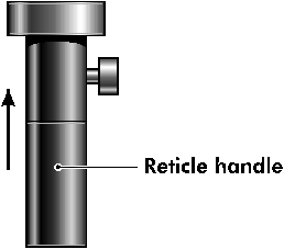
Loosen the clamping screw on the side of reticle holder, and push the handle into the instrument until it stops.
|
Ensure that the two white dots are still perpendicular to the optical axis and tighten the clamping screw.
Note: when inserted, the reticle surfaces may affect the system alignment, resulting in a possible drop in measured beam power of up to 10%. If the system moves out of alignment with the reticle fitted, it may be necessary to re-align before making measurements. This is particularly true when using the Spraytec 450mm lens.
With the reticle correctly positioned, perform a background measurement.
On completion, confirm that the background levels of all active rings are only a few counts above a background taken without the reticle in place. If this is not correct, this may indicate that the reticle glass is dirty or scratched.
Loosen the clamping screw on the side of reticle holder, and withdraw the handle until it stops.
|
Ensure that the two white dots are still perpendicular to the optical axis and tighten the clamping screw.
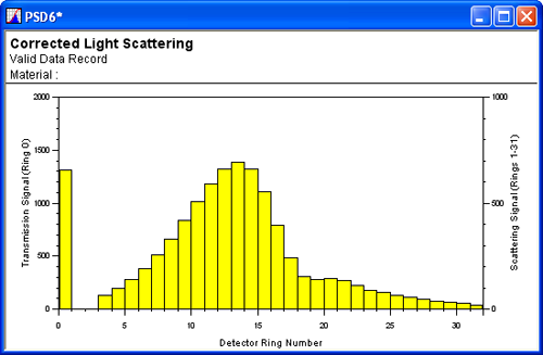
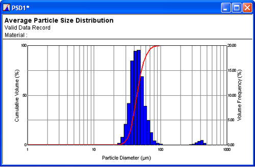
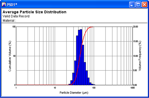
Using the Scattering window, view the corrected scattering pattern for the reticle. This should be smooth and free from any peaks caused by reflections from the glass surface. An example of a good scattering pattern is shown below.
|
If necessary, carefully rotate the reticle angle to achieve a smooth distribution. Only a few small adjustments should be required.
Note: the position of the scattering peak in the distribution will be different for different lens ranges; the pattern shown above is for a 200mm focal length system.
Ensure that the reticle is clamped in place before continuing; otherwise the standard deviations for the measured values will be out of specification.
Create a new Time History File by clicking the New Time History icon:

|
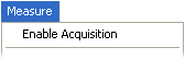
Note: If there is another time history chart active, it will be necessary to transfer measurement control using the Measure-Enable Acquisition menu option. This will cause the measurement control buttons to appear at the bottom of the new time history window.
|
Select the analysis settings using the Edit-Reduction Control menu option.
When the dialogue appears, select the Reduction tab and alter the settings to those indicated in the following table.
Note the values before alteration - these will need to be re-entered after the reticle measurements are complete.
| First Scattering Ring | 4 or lower |
|---|---|
| Last Scattering Ring | 31 |
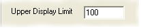
| Lower Absolute Size Bin | 0 |
| Upper Absolute Size Bin | 59 |
| Minimum Particle Size | 1 |
| Maximum Particle Size | 1000 |
| Solution Residual | 0.25 |
| Scattering Threshold | 20 |
| Multiple Scattering Residual | 0.01 |
| Mesh Conversion Factor | 1 |
| Particle Density | 1 |
| Correlation Function Filename of | --- |
Select the Verification tab and alter the settings to those indicated in the following table, remembering to note the original values for future reference.
| Low Signal Error | 50 |
|---|
Select the File tab and ensure that the correct detector response file is selected. Select the correct calibration and imaging files for each lens.
| Lens | 100mm |
|---|---|
| Calibration File | ST10AIAC.CAL |
| Imaging File (Open Bench) | STAAUNIT.IMG |
| Imaging File (Inhalation Cell) | STAASFSE.IMG |
| Lens | 200mm |
| Calibration File | ST20AIAC.CAL |
| Imaging File (Open Bench) | STABUNIT.IMG |
| Imaging File (Inhalation Cell) | STABSFSE.IMG |
| Lens | 300mm |
| Calibration File | ST30AIAC.CAL |
| Imaging File (Open Bench) | STACUNIT.IMG |
| Imaging File (Inhalation Cell) | STACSFSE.IMG |
| Lens | 450mm |
| Calibration File | ST450AIAC.CAL |
| Imaging File (Open Bench) | STAEUNIT.IMG |
| Imaging File (Inhalation Cell) | STAESFSE.IMG |
Note: If the incorrect lens range is selected then the final calculated results will be shifted relative to the verification specifications by a factor of approximately 1.5, 2, 2.25, 3 or 4.5; dependent on which lens is in use and which incorrect lens range has been selected.
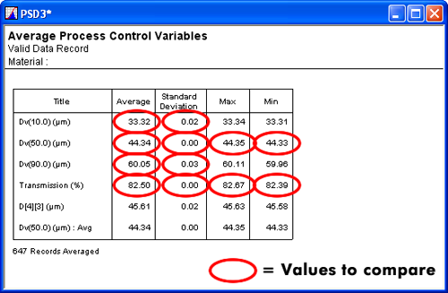
The reticle verification procedure requires measurements to be carried out over a time period of atleast 60 seconds as the stability of the results obtained for at least 60 measurements is assessed. The average Dv10, Dv50, Dv90 and transmission values are then calculated for this time period, requiring an appropriate set of Process Control Variables (PCVs) to be defined.
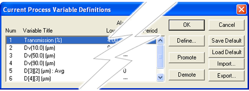
Select Edit-Process Variables from the menu. Ensure that the Dv10, Dv50, Dv90 and transmission are included in the list of 6 process control variables.
|
If this is not the case, use the Define button to redefine the variables to ensure that these are included.
On the active Time History Window control, press the Tag button
 and enter the Reticle type in the Material entry box:
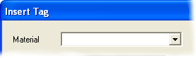
The reticle type can be found on the Reticle Verification sheet.
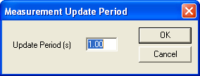
Press the Update button
 and set the update period to 1 second.
|
Start the measurement using the
 button.
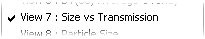
Check that the left axis displays the Transmission, and that the right axis displays the Particle Diameter. To change this:
Right-click on the time history graph and select Size vs Transmission view.
|
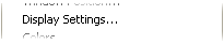
Right-click on this graph, select Display Settings option:
|
Check that:
|
 and select the required variables if necessary.
 and alter these as necessary.
The measurement should continue for at least 1 minute.
Note: When the reticle dot pattern is moved into the beam, the alignment of the reticle may change compared to the orientation set during the background measurement. If this occurs, a small mode may be reported at large particle sizes within the particle size distribution (see below). This is due to reflections within the measurement zone. If this is observed, the reticle position may be rotated until the mode is no longer observed. If the mode persists it may be necessary to move the reticle glass back to the background position (see the Measuring background level section). Realign the Spraytec system with just the bare reticle glass in place, before repositioning the reticle dot pattern within the laser beam.
Note that, in the case of the 450mm lens, it may be necessary to set the first scattering ring to 4 within the Reduction Control settings in order to allow for reflections and misalignment caused by the reticle glass.
|
After 1 minute, stop the measurement. Save the results obtained using the File-save as menu option. Use an appropriate name for the *.pcl file, which references the date of the measurement and the reticle serial number.
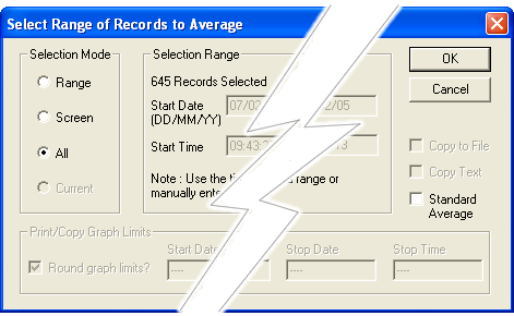
Calculate the average of a recorded time history for the reticle by pressing the Averaging icon:

|
Alter the Selection Mode to All, and ensure that the Standard Average option is not selected.
|
Click OK to display the Averaged result window for all of the records in the time history. Save this average using the File-Save As… menu option. Use an appropriate name for the *.dat file that references the date of the measurement and the reticle serial number.
|
Right-click on the Average result window and select the Cover Page view.
|
|
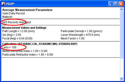
If the number of records averaged is not reported on the Cover Page, right-click on the Cover page window and select the Process Variables / Engineering Units page to obtain this value.
|
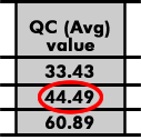
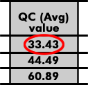
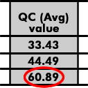
Right-click on the Cover page window and select the Process Variables / Engineering Units page; this will display the reticle measurement results. All verification information will be taken from this page.
|
Check the following is correct to indicate that the reticle verification has passed:
|
|
|
Check that:
If ALL the above checks are passed then the Reticle verification can be deemed to have passed.
Use the following procedure to set-up the Spraytec for routine measurements: