This whitepaper provides an overview of how measurements of various parameters can help to optimize the properties of the electrode material for lithium-ion batteries. A key focus are the electrode materials that influence the performance of the manufactured battery cells. It describes the analytical techniques that support the optimization of these materials in research phase as well as in the quality control phase during the production process.
1. Introduction
Modern batteries like lithium-ion have revolutionized our day-to-day lives from smart mobile devices to pollution free electric cars and intelligent power management solutions. Batteries also hold the potential to being economical alternatives for mass energy storage to compliment renewable energy resources for power grid applications. Despite these successes, gaps in the battery technology remain in terms of safety as well as performance. Equally important is the cost reduction for their mass scale adoption in applications like electric vehicles. These core issues are driving not only the research in new battery materials, but also the improvement in production efficiency to minimize production costs. The imminent issue of rising pollution levels in large cities has generated a great amount of interest in electric vehicles across the globe, making it the main driver for the development of improved battery technology in terms of superior mileage, faster charging time, better safety, and at the same time at a reduced cost. The battery market is expected to grow at a compound annual growth rate of >10% over the next 10 years, primarily driven by the electrification of the transport sector. At the same time, new breakthrough technologies are expected to be commercialized which will boost the energy efficiency, power density and the safety of the rechargeable batteries.
Electrodes used in lithium-ion batteries have a defining influence on their electrochemical performance and are typically manufactured by coating a metal foil substrate with a multi-component slurry made of active electrode particles and conductive additives suspended in a binder solution. Size and shape distribution of electrode particles influences not only the rheology of this slurry in terms of its stability and ease of application, but also defines the quality parameters of the resulting coat like thickness uniformity, packing density and porosity. These, in turn, impact key battery performance parameters, such as ion transfer rate and battery recharge time.
1.1 Understanding electrode manufacturing
Battery slurries are multi-component suspensions of active particles in a continuous polymeric solution. Key components include:
- Active electrode materials : complex lithium compounds such as LiMn x Fe 1 - x PO4 (LMFP), LiMn 2 O 4 (LMO), LiNi x Co y Al 1 -x-y O 2 (NCA) and LiNi x Mn y Co 1 -x-y O 2 (NMC) that accept and release lithium-ion in the electrochemical reactions inside a battery cell are used as cathode materials. Most common process of producing cathode materials is liquid phase co-precipitation of metal hydroxides followed by solid state fusion with a Li compound, schematically shown in figure 1. graphite is the most commonly used anode material, although other candidates like Si or graphene modifications are also in the development phase.
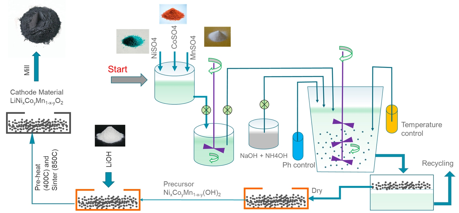
Figure 1: Schematic representation of NMC cathode materials production process - Conductive additives : fine particles of, for example, carbon black or graphite, aid current flow within the electrode, thereby enhancing performance.
- Polymeric binder : polymeric materials such as polyvinylidene difluoride (PVDF) bind the active electrode particles together in the finished electrodes and ensure adhesion to the metal substrate.
- Solvent : dissolution medium for the binder to form the continuous phase of the coating slurry; N-methyl-2-pyrrolidone (NMP) is routinely used because of its compatibility with PVDF.
The figure below illustrates the electrode manufacturing process. Slurry formulation involves dissolution of the binder in the solvent, followed by dispersion of the powder components (synthesized electrode material and the carbon black) which may or may not be pre-blended. The resulting slurry is then applied to a metal foil using a coating process such as blade coating, slot die coating or spray coating. Drying and calendaring produces the finished electrode – calendaring being a roller compression process designed to control porosity.
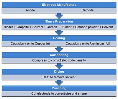
Figure 2: Electrode manufacturing is a multi-step process with performance influenced by the bulk rheological properties of the process streams and physical properties of the constituent ingredients, such as particle size and shape.
The optimization of electrode manufacturing processes is therefore a complex challenge, one that relies in the first instance on robust characterization of the components of the slurry, in isolation and in combination, with various complementary analytical techniques. The information of the materials revealed by these analytical tools lay a foundation for optimizing the properties of the slurry ingredients and helps to meet the dual goals of desirable electrochemical performance coupled with high electrode manufacturing efficiency. In this whitepaper, we discuss the various technologies used:
• Laser diffraction for measuring particle sizes
• Automated imaging for quantifying particle shape
• Gel permeation chromatography for characterizing binders
• X-ray diffraction to define crystal structure of electrode materials
• X-ray fluorescence for analyzing chemical composition and detecting elemental impurities
• Micro-electrophoresis for quantifying stability and surface interactions.
In each case, we summarize how the approach works, discuss the key factors involved in selecting operational parameters, and explain the benefit of the resulting data for enhancing the battery performance.
2. Particle size
2.1 Particle Size: why is it important?
With regard to the electrode manufacturing process, particle size and size distribution are highly relevant for the optimization of:
- Precursor Yield : Precursor particles nucleate, grow and agglomerate to form large secondary particles in the slurry that is stirred at high rotation speed. This process can take anywhere between 20-30 Hrs, depending on the process efficiency. Monitoring the size evolution of particles in the slurry can provide insight into the particle formation process and can be used to optimize parameters like Ph, rotation speed, temperature etc. to achieve high production efficiency.
- Electrochemical performance : The size of active electrode particles directly influences two key performance parameters of a battery: power and storage capacity. Battery power is determined by the rate of reaction between active materials and the electrolyte and can therefore be increased by decreasing particle size thereby increasing specific surface area available for reaction. Storage capacity, on the other hand, is a function of the volume of electrolyte within the cell and is detrimentally impacted by reducing particle size since this leads to enhanced dissolution of surface metal ions in the electrolyte as well as the reduced porosity in the electrode for Li-ion migration.
- Solids loading: The volume fraction of solids within the slurry directly affects its viscosity. High solids loading may be preferable from the perspective of, for example, reducing the drying time of the applied coating, but will tend to result in increased suspension viscosity which may be disadvantageous in terms of the application process. Decreasing particle size or narrowing the polydispersity (particle size distribution) of the suspended phase will further increase suspension viscosity for a given solids loading.
- Slurry stability : From stability perspective, increasing particle size tends to increase the risk of sedimentation or settling in a gravitationally dominated system. Maintaining a homogeneously dispersed slurry can therefore be easier with relatively fine particles. On the other hand, fine particles may be prone to agglomeration and/or flocculation, forming larger particles with a tendency to settle resulting in uneven coat and ultimately compromising the electrochemical performance.
The particle size, thus, needs to be optimized to balance many competing aspects that influence the overall performance in one way or the other.
2.2 Particle Size Measurement: Laser Diffraction
With a measurement range that runs from 0.01 to 3500 µm, laser diffraction is the particle sizing technology of choice for most battery manufacturing applications – starting from precursor to the final milled electrode materials. Laser diffraction systems determine particle size from the resulting light scattering pattern as a collimated laser beam passes through the sample, as shown in figure 3. Large particles scatter with high intensity at narrow angles relative to the incident beam, while smaller particles generate a weaker signal but extending to wider angles. Laser diffraction analyzers calculate the particle size distribution of the sample from the measured angular dependence of the scattered light using an appropriate theory of light scattering, generally the Mie theory.
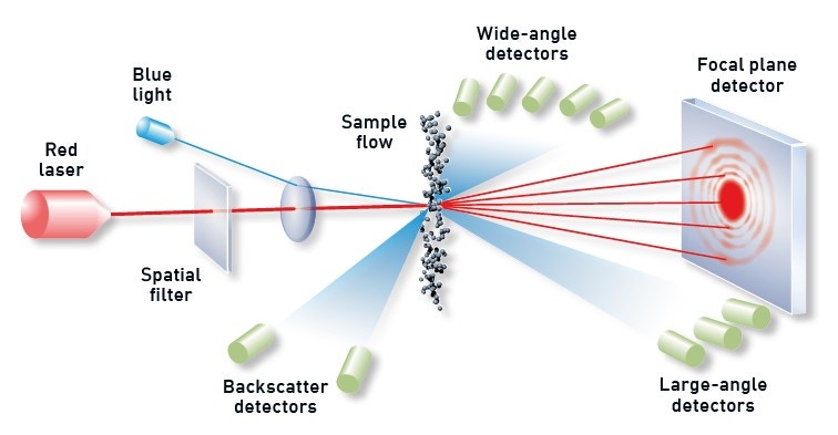
Figure 3: Illustration showing the principle behind a laser diffraction measurement with diffracted light from dispersed particles picked up by optimally positioned detectors.
Modern laser diffraction systems are highly automated, to the point of push button operation, and offer high throughput analysis with minimal manual input. Typical particle size distributions as obtained from laser diffraction experiments are shown in figure 4. Apart from the laboratory-based laser diffraction systems, there are also online process systems that deliver real-time monitoring of particle size for automated process control. These can be used either for the monitoring of particle size evolution in precursor slurry or in the control of electrode materials size right after the mill.

Figure 4: Typical particle size distribution measurements using a laser diffraction system on cathode and anode materials synthesized under different conditions.
3. Particle Shape
3.1 Particle shape: Why is it important?
The role of particle shape in battery electrode materials is often ignored or underestimated. However, this may be the key to unlock full potential of a given battery material to be translated into the best performing battery. Particle shape affects slurry rheology as well as the electrode coating in terms of packing density, porosity and uniformity. Particles shape also influences the production efficiency of precursor materials. To achieve the highest level of battery performance, manufacturers must also understand and optimize the particle morphology. In general, particle shape can influence the following:
- Precursor Yield : Apart from particle size, production efficiency of precursor also depends on particle shape. Highly irregular or elongated particles will re-dissolve or break due to the hydrodynamic force of the slurry that is stirred at high rotation speed, thus impeding the growth of large secondary particles. Monitoring the shape of precursor particles and its optimization can enhance precursor production efficiency to the highest levels.
- Electrochemical performance : The shape of active electrode and conductive additive particles influences their packing behavior on the metal substrate and how they interact with the electrolyte when incorporated into a battery. Research indicates that the use of spherical, as opposed to more irregularly shaped and closely joined, particles delivers an increase in high rate discharge performance, particularly for thicker electrodes. More generally, greater sphericity is associated with easy permeation of the electrolyte within the electrode enabling increased reaction rate and consequently the higher battery power. Optimizing particle size and shape in tandem can therefore be a beneficial strategy for accessing superior electrochemical performance
- Solids loading : By influencing how particles pack together, particle shape also affects the relationship between solids loading and suspension viscosity. Smoother particles result in lower shear viscosity than those of equivalent size with a rough surface, a feature than can be quantified via the metric convexity. Particles with low convexity have a convoluted outline that increases their specific surface area relative to smoother analogues and tends to increase mechanical resistance to flow within a suspension.
- Slurry behavior : In reference to electrode slurry, the elongated particles tend to be associated with higher viscosity than those that are more spherical, under low shear conditions. However, the converse is true at high shear, with elongated particles often exhibiting high shear-thinning behavior due to orientation in the direction of flow, which results in extremely efficient packing.
3.2 Particle shape measurement: Automated imaging
Automated imaging (suitable for particles from ~ 0.5 µm to > 1 mm) offers both particle size and shape measurement on statistically rich ensemble of particles – either as dry powder dispersion or as dispersion in a liquid medium. Automated imaging is an efficient technique for generating data for the comprehensive optimization of electrode particle morphology. Automated imaging systems capture individual images of tens of thousands of particles in a dispersed sample in just a few minutes. The figure below shows typical particle morphologies as revealed with automated imaging.
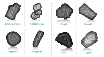
Figure 5: Particle morphology differentiation as revealed with automated imaging
Multiple size and shape parameters are calculated for each individual particle and are used to build up statistically significant number-based distributions. Circular equivalent diameter (figure 6), defined as the diameter of a circle having same area as the particle, is often used to define the size of non-circular particles.
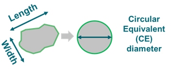
Figure 6: Length, width and CE diameter of an irregular particle.
The most commonly used shape parameters are:
• Circularity = particle perimeter/perimeter of an equivalent area circle, or
• High sensitivity (HS) circularity = (perimeter/perimeter of an equivalent area circle)2
Circularity is often used to measure how close a particle is to a perfect sphere. However, care should be exercised in interpreting the data, since any deviations could be due to either changes in surface roughness or physical form, or both.
Physical form can be measured in terms of elongation, defined as:
Elongation = 1 – (width/length)
Whereas, surface roughness can be measured using convexity, defined as:
Convexity = convex hull perimeter / actual particle perimeter
In simple terms, the convex hull perimeter is calculated from an imaginary elastic band which is stretched around the outline of the particle image, as shown in figure 7. Convexity value of 1 means smooth particle and lower values meaning larger roughness.

Figure 7. Closed loop in green color is the convex hull perimeter for the corresponding shape.
Shape parameters for three different particle types are shown in figure 8.
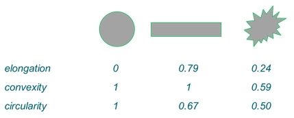
Figure 8: Elongation, convexity and circularity of three different particle types.
Automated imaging eliminates the subjectivity associated with manual microscopy, and at the same time significantly reduces the measurement times, thereby making it easy to systematically investigate the effect of particle shape on battery electrode performance.
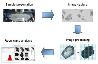
Figure 9: General workflow for an automated imaging measurement
The latest advances in automated imaging technology delivers faster measurements, enhanced sensitivity, and easier method development, supporting efficient application of the technique across a wide range of industrial applications. In comparison to SEM, automated optical imaging provides much superior statistical accuracy while analyzing particles in 1-1000µm range. Figures 10 - 11 show particle images and the derived size and shape (HS circularity) on 3 different cathode materials that were also measured with laser diffraction (figure 4). Additional information on the shape of particles can be used to explain the differences in electrochemical performance of finished electrodes made from these cathode materials.
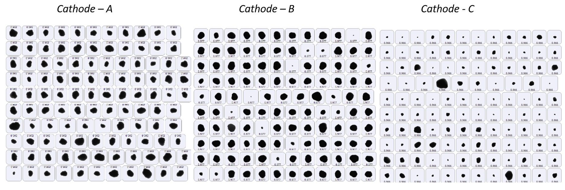
Figure 10: An example of particle images captured with automated imaging on three cathode materials synthesized under different conditions.

Figure 11: Particle size (left) and shape (right) analysis of cathode materials (images in figure 10), using automated imaging. HS circularity is a measure of irregularity in particle shape – value of 1 means perfectly circular and smaller values representing larger deviation from circularity. Cathode B and C are highly irregular with large variance in HS circularity values. Cathode C also has a broad size distribution with some over-sized particles.
4. Crystalline phase
4.1 Why analyze crystalline phase?
Crystalline phase defines the structure of materials at atomic scale – the scale at which ionic or electronic transport happens or is hindered. Crystalline phase has some key attributes which define the overall electrode material quality and its suitability for the battery cell manufacturing:
- Crystalline phase composition : Currently used cathode materials (LFMP, NCA, NMC) have varying composition of metals like Ni, Mn, Co, Al etc. Usually these are prepared using techniques like co-precipitation and solid-state reaction. Having the correct composition of starting materials is not enough to ensure correct composition of final cathode material, as the reactants may not fuse completely. Correct composition of the finished cathode material can only be ensured through the measurement of underlying crystalline phase. Each crystalline phase has unique periodic atomic structure, and the measurement of periodic spacings (known as lattice parameter) can give insight into the actual material composition.
- Crystallite size : Crystallite refers to a coherent crystal domain with uninterrupted periodic atomic structure. Usually “particle” is a much larger entity consisting of many crystallites.
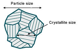
Figure 12: Illustration showing crystallite and particle
Figure 12 illustrates the difference between the two. In battery materials which are prepared using co-precipitation method, particle formation happens via nucleation and growth of primary particles followed by agglomeration to larger secondary particles. In this kind of growth mechanism, primary particles most likely are same as the “crystallite” and the agglomerates represent the “particle”. Thus, measurement of crystallite size in cathode materials manufactured via co-precipitation can give a fair estimate of the primary particle size, which plays an important role in lithium-ion transport. - Degree of graphitization : Graphite is the commonly used anode material in lithium-ion batteries. Graphite can either be natural or synthetic. Synthetic graphite is preferred due to its superior consistency and purity compared to natural graphite. Degree of graphitization and orientation index are important attributes of synthetic graphite, closely linked to its energy density. Degree of graphitization is a measure of how close the synthesized material is to the pure natural graphite, whereas, orientation index is a measure of the tendency of graphite particles to align along some specific crystallographic direction.
4.2 Crystalline phase measurement: X-ray diffraction (XRD)
X-ray diffraction (XRD) is a routinely used technique to analyze crystalline phase properties and thus the quality of synthesized powder materials. It can measure phase purity, phase composition and the crystallite size. Phase analysis using XRD can also be used to derive parameters like Degree of graphitization or the orientation index in graphite anode.
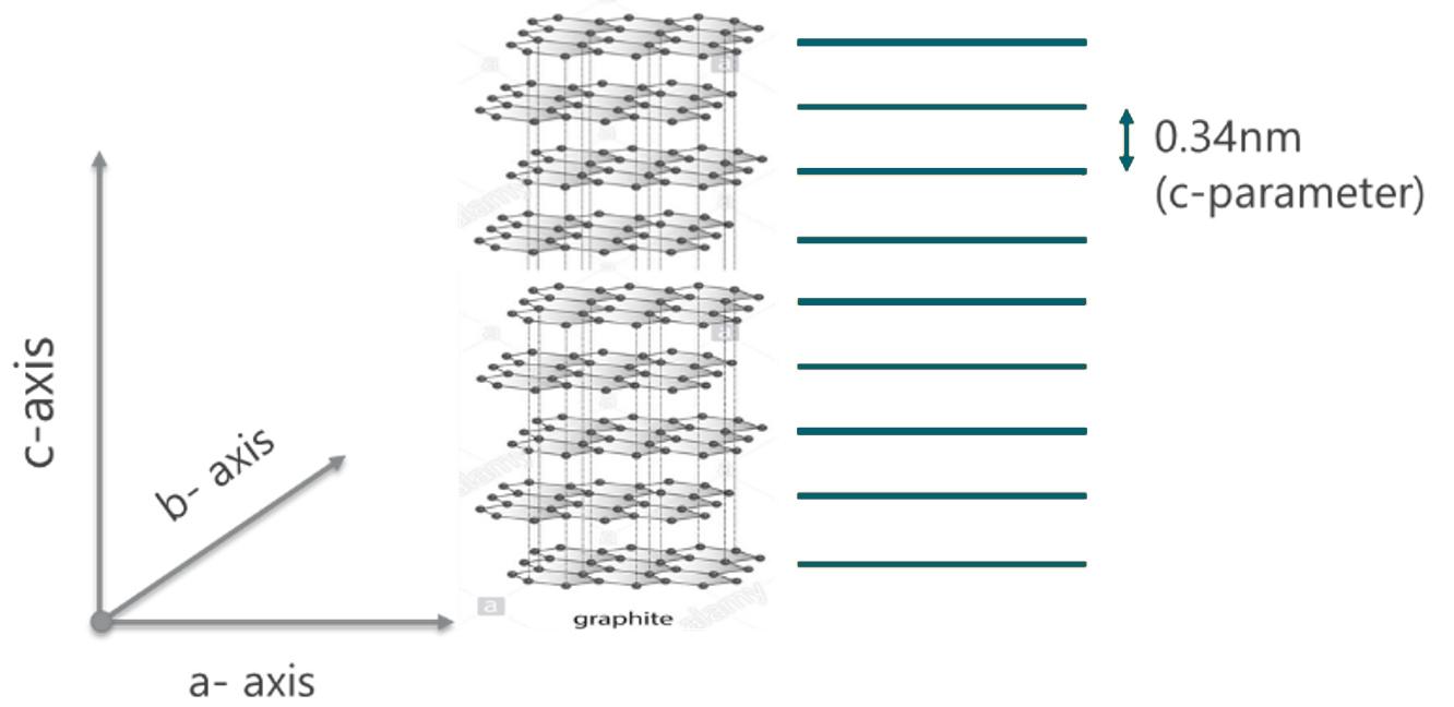
Figure 13: A representation of graphite crystalline phase investigated by XRD and derivation of c-parameter
Based on the principle of X-ray scattering and diffraction, XRD investigates crystal structure at atomic scale. One parameter derived from XRD measurement is the lattice parameter (periodic spacing between the crystal planes) as shown in figure 13. A pure phase would have a unique set of XRD peaks corresponding to the unique value of lattice parameters representing this crystalline phase. Typical XRD pattern of an LMFP sample is shown in figure 14. As the material composition changes, the lattice parameter also changes – this causes a shift in the peak position of corresponding XRD pattern. Peak shifts in LMFP samples as the Mn composition changes is shown in figure 15.
The material composition can thus be derived from the measured shift in the XRD peak position. Crystallite size can be estimated from the width of the XRD peak – larger the peak width, smaller is the crystallite size. Figure 16 shows how the crystallite size increases with Mn composition in LMFP samples. Likewise, degree of graphitization can be measured form the shift in the sample peak position relative to the ideal graphite peak position. Degree of graphitization obtained from XRD measurement in one such synthetic graphite sample is shown in figure 17. Orientation index can be estimated by comparing the relative intensity of peaks in the sample compared to theoretical relative peak intensities in pure graphite.
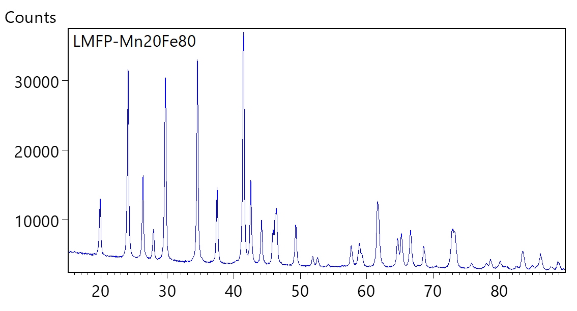
Figure 14: Typical XRD pattern of a Lithium Manganese Iron Phosphate cathode material
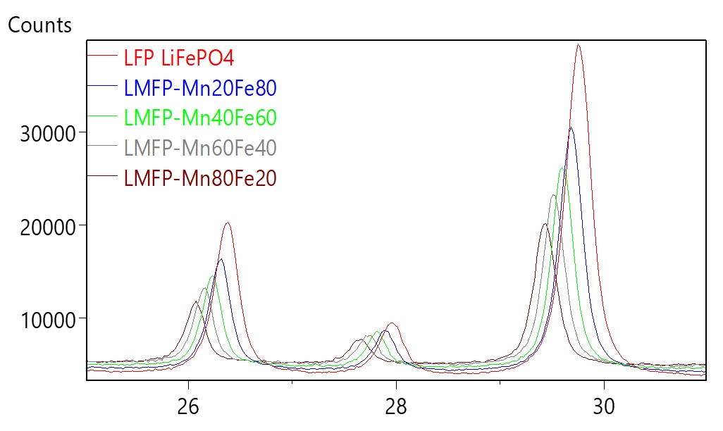
Figure 15: Shift in XRD peak position as a function of cathode composition

Figure 16: Derived Mn content (left) and the crystallite size (right) from the measured XRD data.
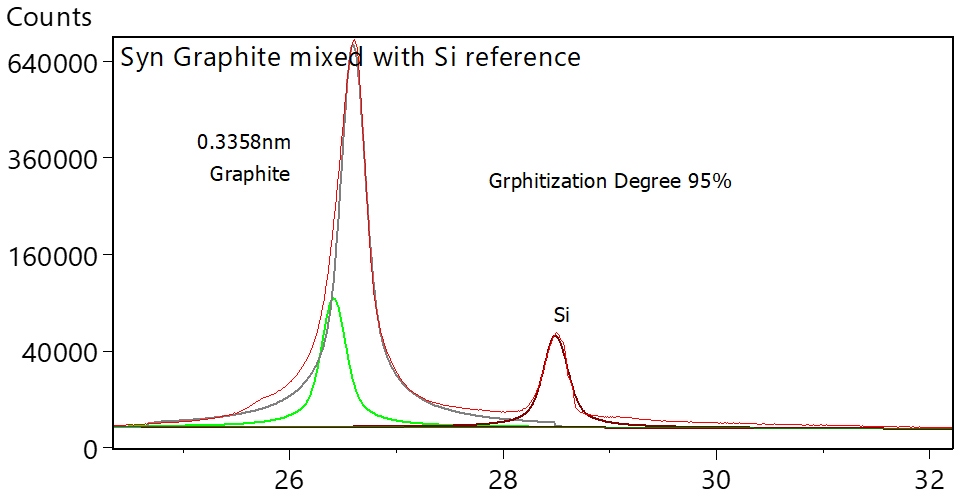
Figure 17: Degree of graphitization in a synthetic anode, derived from XRD data. Si powder was added to the sample as peak position reference standard to eliminate inaccuracy arising from error in instrument calibration.
5. Chemical composition and elemental impurities
5.1 Why analyze chemical composition and impurities?
Ensuring that synthesized material has the right chemical (elemental) composition is the first step towards maintaining consistent product quality. In cathode manufacturing, measurement of chemical composition is desirable at three successive production stages:
- Salt Solution : In the case of co-precipitation (like in NMC cathode precursor) the starting material is the salt solution of metals in desired relative concentrations. A continuous production process mandates regular monitoring of the metal concentration in the salt solution to ensure that the right slurry formulation is maintained throughout.
- Cathode Precursor : Once the precursor material is formed and filtered out, it is important to check that the co-precipitation has led to the desired chemical composition of the precursor.
- Electrode Materials : once the synthesis of the cathode and anode materials has been finished, these materials should be checked both for chemical composition as well as other impurities. Undesired impurities, which are usually at sub-percent to ppm levels, can adversely affect the storage capacity, cycle durability or the safety of the manufactured battery.
5.2 Chemical composition and impurity measurement: X-ray Fluorescence (XRF)
A simple and fast way to analyze chemical composition and impurities in battery materials is X-ray fluorescence (XRF). XRF can measure elemental composition and impurities both in powder samples (presented as pressed pellet or as fused beads) and in liquid solution / suspension, making it an ideal tool both for precursor slurry as well as dry cathode or anode powder analysis. The often used inductively coupled plasma (ICP) analysis is not always the best tool for this. Requiring sample digestion, dilution, and daily calibration, ICP is labor-some, and therefore an expensive elemental analysis method in battery production process. Particularly for the chemical composition analysis, where the main elements are at a few percent level, XRF can measure samples as such, without any need for dilution. Other advantages of XRF are small footprint, ease of operation, no need of high purity gases, and minimal expertise requirement. Accurate quantitative analysis in XRF requires calibration with standards. However, calibration on XRF can last for more than a year before the need of recalibration. A typical calibration curve on the salt solution used in NMC precursor slurry is shown in figure 18, whereas table 1 lists the accuracy and linearity as obtained in the XRF measurements.
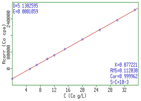
Figure 18: Typical example of a linear response of XRF signal as a function of Co concentration in NMC sulfate precursor slurry.
 Table 1: Typical accuracy and linearity of chemical composition as derived from XRF measurement. Concentration listed here are in gram/liter (g/L).
The basic principle of XRF analysis is simple. If we expose a sample with a beam of X-rays, it will cause secondary X-rays (fluorescence) to be generated within the sample. These X-rays have energies (or wavelength) which are characteristic of the elements present in the sample. In other words, by measuring the energies Ei (or wavelengths l i ) of X-rays that come out of the sample, we can tell what elements are present in the sample. The characteristic energies for each element in the periodic table are known and well documented. For example, if 7.7 keV X-ray photon comes out of the sample then Co is present and 8.3 keV photon means Ni is present and so on. Under carefully controlled conditions, we can count the number X-rays photons coming from each element over a period, say in one minute, and from this we can calculate the proportions of each element in the sample.
Powder sample can be presented either as a fused glass bead or a pellet of pressed powder. Beads are made by heating the specimen together with a flux, typically lithium tetraborate, at about 1100 C° to form a glass disk. This approach has the advantage that the specimen is then a homogeneous material free from underlying matrix, allowing more accurate elemental analysis.
Pressed pellets are made by grinding the specimen finely and compressing the resulting powder to form a pellet. This pellet is then analyzed directly. Preparing pressed pellets is quicker and easier than preparing glass beads, but the specimen is then a heterogeneous material. This makes the calculation of elemental composition from the measured XRF signal more complex, although modern analysis software can simulate and apply various corrections resulting in fairly accurate analysis. XRF is at the heart of the control of the production process in any modern chemical industries and is central to the ability of the electrode manufacturers to produce a consistent product quality.
Broadly speaking, there are two types of X-ray spectrometers – Energy Dispersive (EDXRF) and Wavelength Dispersive (WDXRF). The geometrical differences between the two types of spectrometers are shown in the figure below.
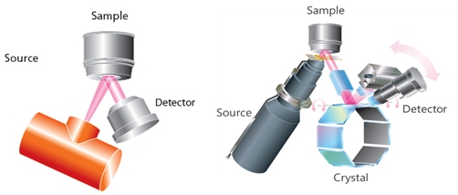
Figure 19: EDXRF (left) and WDXRF (right) geometries
EDXRF – In an EDXRF system (2D optics), X-rays irradiate the sample and the fluorescence coming out of the sample is measured by an energy dispersive detector. Usually, the detector is Peltier cooled Si (Li) or Ge Solid state detector. EDXRF usually has high sensitivity for high z-elements and can typically measure elements from F to U. Some advanced EDXRF can measure elements down to Carbon (C). As EDXRF measures all the elements simultaneously, low source power is enough to achieve high counting statistics. Usually, the limiting factor in EDXRF is the count rate handling of the detector and high source power may saturate the detector and thus not recommended.
WDXRF – In WDXRF also, the X-ray tube irradiates the sample and the fluorescence coming out of the sample are detected by the detector. However, the detection system comprises of a collimator, a diffraction crystal and a detector. X-rays coming from the sample pass through a collimator and fall on a crystal. Crystal disperses different wavelength X-rays in different directions. Another collimator placed at a certain angle selects one of the wavelengths that gets measured by the detector. WDXRF has superior sensitivity to light elements and is recommended when light elements below Na are to be measured with high accuracy. However, WDXRF requires high source power as the measurement is sequential. Despite high power, the detector in WDXRF does not saturate as the beam is pre-filtered by the crystal and fluorescence form only one specific element falls onto the detector at a given time.
6. Comprehensive binder characterization: Gel permeation chromatography
A core technique for polymer analysis, gel permeation chromatography (GPC) / Size Exclusion Chromatography (SEC) system can be used to measure a range of properties including absolute molecular weight, molecular size, intrinsic viscosity, branching and other polymer parameters. These properties define polymer performance and are therefore pivotal when it comes to binder selection.
In size-exclusion chromatography, molecules are separated according to their hydrodynamic radius as they enter and exit the pores of a porous gel packing matrix in the column (Figure 17). Like other HPLC-based techniques, this involves the use of a pump, column and at least one detector to measure the sample as it elutes. Modern integrated GPC systems typically incorporate a refractive index and/or UV detector, a light scattering detector and a viscometer. This is a powerful array, optimally matched to the requirements of most industrial applications that enables measurement of all the parameters outlined above. The light scattering detector allows the determination of the absolute molecular weight of a sample independent of column retention volume or reference standards, offering real insight into the effects of sample modifications.
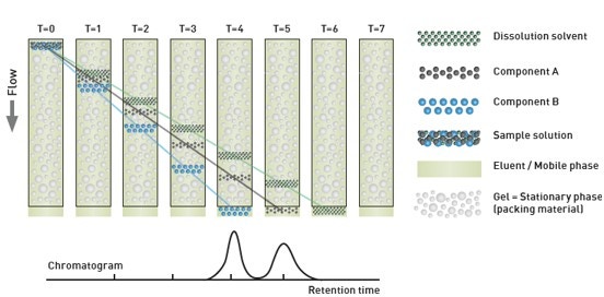
Figure 20: Illustration showing the separation mechanism in a GPC column and the reported chromatogram following UV/RI detection of eluted fractions.
For battery manufacturers, GPC can be used to comprehensively characterize the binder to develop a solution with optimized rheological properties. This is particularly the case for researchers looking to replace NMP, a toxic, flammable, expensive solvent, with, for example aqueous-based systems having comparable performance. Polymers exhibit complex behavior in solution, especially at higher loadings when individual polymer coils no longer have enough space to avoid interaction. Above a critical concentration, entanglement between neighboring coils becomes inevitable and the viscoelasticity of the overall system is substantially altered. Molecular size and intrinsic viscosity can be used to determine the concentration at which this transition occurs for any given polymer/system, thereby providing valuable information to support binder selection and usage.
7. Measuring zeta potential to quantify slurry stability: Micro-electrophoresis
Zeta potential is a measure of the magnitude of electrostatic repulsion or attraction at the boundary layer surrounding a particle in suspension and is therefore directly indicative of system stability (see figure 21). It is measured using the technique of Laser Doppler electrophoresis, electrophoresis being the motion the particles exhibit when subjected to an electrical field. In zeta potential measurements, an electric field is applied to a dispersion and the particles within it then move at a velocity that is related to their zeta potential. The velocity of movement can be measured using a laser interferometric light scattering technique to determine electrophoretic mobility, from which zeta potential/zeta potential distribution can be determined. In an analogous way, measurements of surface zeta potential can also be made using tracer particles to measure electro-osmosis close to a sample surface.
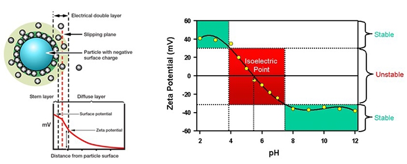 Figure 21: Zeta potential (left) determines whether particles will repel or attract one another when held in suspension. Zeta potential usually depends on solution Ph (right).
By quantifying the balance of attractive and repulsive forces that particles experience as they approach one another, zeta potential can provide an indication of suspension stability in systems where electrostatics, rather than gravity, dominates. A zeta potential close to zero is associated with system instability and a tendency towards aggregation, while a pronounced negative or positive value
(+/- 30mV) is indicative of electrostatic stability. Zeta potential can affect the rheological behavior as well, for instance increased repulsion is likely to increase low shear viscosity in concentrated systems due to a larger effective phase volume. Under strong attraction, on the other hand, aggregation can lead to the formation of a particulate gel with a high yield stress, if the particles are concentrated enough to form a network.
For battery manufacturers, measurements of zeta potential are therefore valuable for tailoring slurry properties to meet stability goals. In addition, zeta potential measurements can provide insight into the interactions between the slurry and the metal substrate, supporting the development of slurries that will adhere effectively to the substrate during the application process. Again, this is particularly relevant in the evolution of aqueous technologies with wetting performance comparable to that achieved with established NMP-based analogues. In addition, zeta potential of the precursor slurry can estimate the tendency of primary precursor particles to agglomerate and form larger secondary particles, thereby providing a tool to optimize slurry parameters to enhance production efficiency.
8. In conclusion
The manufacturing of electrodes for lithium-ion batteries is a complex, multi-step process and presents a significant optimization challenge. Comprehensive analytical characterization with a range of complementary techniques provides a secure foundation for tackling this challenge, bringing value to both the individual components and the multicomponent streams. All the techniques reviewed here have a place in the analytical toolkit for battery electrode manufacturers and all can play a vital role in meeting the targets of optimal production efficiency coupled with desirable electrochemical performance.
REFERENCES:
1 The influence of particle shape on the characteristics of coating films for battery electrodes. Malvern Panalytical application note.
2 Battery research and quality control solutions, Malvern Panalytical battery brochure.
3 Theory of XRF, book by Malvern Panalytical
4 XRD for the analyst, book by Malvern Panalytical
5 A basic guide to particle characterization, Malvern Panalytical white paper
6 Duffy, J., Controlling Suspension Rheology. Chemical Engineering. 2015. Available at: https://view.imirus.com/8rLRGj2mK8G/document/11234/1
