
In recent years, metal additive manufacturing (AM) has transitioned successfully from a prototyping tool to a still new, but established and economically viable, choice for component production. Indeed, as the aerospace, energy, automotive, medical, and tooling industries have embraced this technology [1], annual sales of metal AM machines have risen from less than 200 in 2012 to almost 2,300 in 2019. Alongside this trend, the use of AM in manufacturing is also driving an increase in the proportion of the market dedicated to metal materials. This segment is expected to account for a quarter of the whole manufacturing market by 2023 [2].
Powder bed AM processes such as selective laser melting (SLM), electron beam melting (EBM), and binder jetting offer certain advantages over alternative powder metallurgy methods, including design flexibility and potential for high material-use efficiency. These processes are particularly suitable for producing small to medium volumes of relatively small components, as well as enabling the creation of new, complex parts that were previously unachievable. As these technologies are adapted to enable larger components and higher throughputs, the development of AM machines is an increasingly important focus area. However, there is now also an equal emphasis on the properties of the powders used [3].
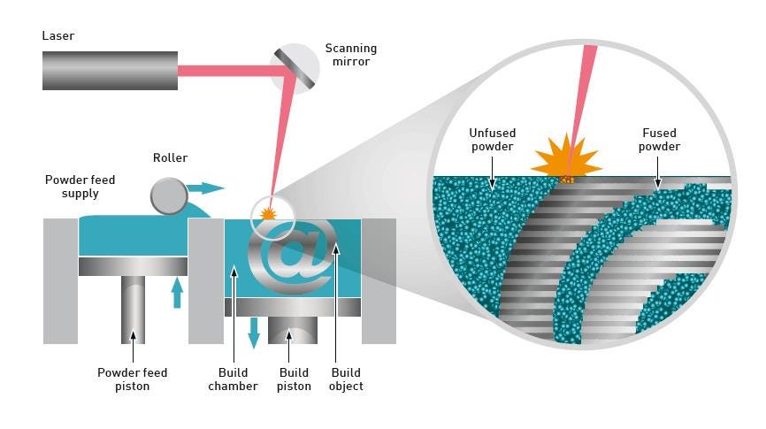
Figure 1: Powder bed AM processes such as SLM require rapid, even powder spreading and effective recycling of the excess powder.
AM processes typically operate with ‘fixed’ parameters for a specific application; most currently available machines offer little opportunity for responsive control. As such, inconsistent properties in the input material will directly translate to inconsistent properties in the finished component. Poor powder quality can produce defects in the end part including pores, cracks, inclusions, residual stresses, and sub-optimal surface roughness, as well as compromising throughput. To avoid these issues, manufacturers must understand the relationship between material properties, processing performance, and end-component properties [3].
Chemistry is paramount in metal AM powders. A powder needs to be compatible with the alloy composition of the material specified. The grade must also be carefully selected to control the interstitial elements present such as oxygen or nitrogen, as well as particulate contaminants which can impact the properties of the finished part. Beyond chemistry, it is the physical characteristics of a metal powder, such as packing density and flowability, that determine AM performance. Powders that pack consistently with high density are associated with the production of consistent-quality components with fewer flaws, while good flowability enables the powder to spread evenly and smoothly across a bed to form a uniform layer with no air voids [3].
Bulk density and flowability are directly, though not exclusively, influenced by morphological characteristics such as particle size and shape, as illustrated in Figure 2. For instance, smooth, regular-shaped particles typically flow more easily than those with a rough surface or an irregular shape [4]. This is because rougher surfaces result in increased interparticle friction, while irregularly shaped particles are more prone to mechanical interlocking; both effects decrease flowability. Similarly, spherical particles tend to pack more efficiently than those that are irregular, giving rise to higher bulk densities [5].
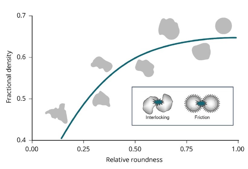
Figure 2: Smooth, regularly shaped particles tend to flow more easily than those that are irregular and/or rougher, because of reduced interparticle friction and a lower risk of mechanical interlocking.
When it comes to particle size, AM metal powders must be fine – for example, so that they can form a powder bed just tens of microns thick. However, these ‘fines’ can be problematic for health and safety, as well as flowability. Because the forces of attraction between particles increase with decreasing particle size, finer powders usually flow less freely than coarser analogs. Optimizing particle shape can help to mitigate this effect [4, 6]. Particle size and particle size distribution also influence packing, as illustrated in Figure 3. Specifically, distributions including both coarse and fine particles, with finer particles filling the interstices left by larger ones [5], enable maximum packing density.
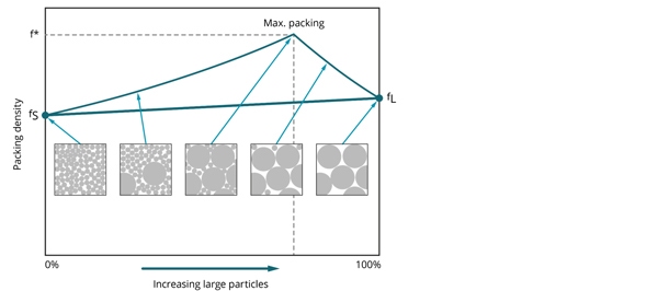
Figure 3: Packing density reaches a maximum when the particle size distribution includes both fine and coarse particles.
To continue reading this whitepaper, please login or register for a free account
In recent years, metal additive manufacturing (AM) has transitioned successfully from a prototyping tool to a still new, but established and economically viable, choice for component production. Indeed, as the aerospace, energy, automotive, medical, and tooling industries have embraced this technology [1], annual sales of metal AM machines have risen from less than 200 in 2012 to almost 2,300 in 2019. Alongside this trend, the use of AM in manufacturing is also driving an increase in the proportion of the market dedicated to metal materials. This segment is expected to account for a quarter of the whole manufacturing market by 2023 [2].
Powder bed AM processes such as selective laser melting (SLM), electron beam melting (EBM), and binder jetting offer certain advantages over alternative powder metallurgy methods, including design flexibility and potential for high material-use efficiency. These processes are particularly suitable for producing small to medium volumes of relatively small components, as well as enabling the creation of new, complex parts that were previously unachievable. As these technologies are adapted to enable larger components and higher throughputs, the development of AM machines is an increasingly important focus area. However, there is now also an equal emphasis on the properties of the powders used [3].
Figure 1: Powder bed AM processes such as SLM require rapid, even powder spreading and effective recycling of the excess powder.
AM processes typically operate with ‘fixed’ parameters for a specific application; most currently available machines offer little opportunity for responsive control. As such, inconsistent properties in the input material will directly translate to inconsistent properties in the finished component. Poor powder quality can produce defects in the end part including pores, cracks, inclusions, residual stresses, and sub-optimal surface roughness, as well as compromising throughput. To avoid these issues, manufacturers must understand the relationship between material properties, processing performance, and end-component properties [3].
Chemistry is paramount in metal AM powders. A powder needs to be compatible with the alloy composition of the material specified. The grade must also be carefully selected to control the interstitial elements present such as oxygen or nitrogen, as well as particulate contaminants which can impact the properties of the finished part. Beyond chemistry, it is the physical characteristics of a metal powder, such as packing density and flowability, that determine AM performance. Powders that pack consistently with high density are associated with the production of consistent-quality components with fewer flaws, while good flowability enables the powder to spread evenly and smoothly across a bed to form a uniform layer with no air voids [3].
Bulk density and flowability are directly, though not exclusively, influenced by morphological characteristics such as particle size and shape, as illustrated in Figure 2. For instance, smooth, regular-shaped particles typically flow more easily than those with a rough surface or an irregular shape [4]. This is because rougher surfaces result in increased interparticle friction, while irregularly shaped particles are more prone to mechanical interlocking; both effects decrease flowability. Similarly, spherical particles tend to pack more efficiently than those that are irregular, giving rise to higher bulk densities [5].
Figure 2: Smooth, regularly shaped particles tend to flow more easily than those that are irregular and/or rougher, because of reduced interparticle friction and a lower risk of mechanical interlocking.
When it comes to particle size, AM metal powders must be fine – for example, so that they can form a powder bed just tens of microns thick. However, these ‘fines’ can be problematic for health and safety, as well as flowability. Because the forces of attraction between particles increase with decreasing particle size, finer powders usually flow less freely than coarser analogs. Optimizing particle shape can help to mitigate this effect [4, 6]. Particle size and particle size distribution also influence packing, as illustrated in Figure 3. Specifically, distributions including both coarse and fine particles, with finer particles filling the interstices left by larger ones [5], enable maximum packing density.
Figure 3: Packing density reaches a maximum when the particle size distribution includes both fine and coarse particles.
Most metal powders used in AM are produced by gas atomization. In this process, a feedstock is melted in a crucible and then ejected through a nozzle into a high-pressure gas stream (usually argon or nitrogen), breaking the molten stream into droplets. The size of particles produced by gas atomization can be controlled by varying process parameters such as gas pressure, melt properties, nozzle design, and gas-metal ratio. However, the resulting powder is not ideal for AM processes, which optimally require a narrower particle size distribution to produce a consistent powder layer of the correct thickness, as illustrated in Figure 4. Various post-atomization processes can be applied to obtain the required size fraction. These processes include ‘scalping’ to remove oversize particles, followed by either air classification or sieving. The resulting lower atomization yield is one factor that increases the cost of AM powders [3].
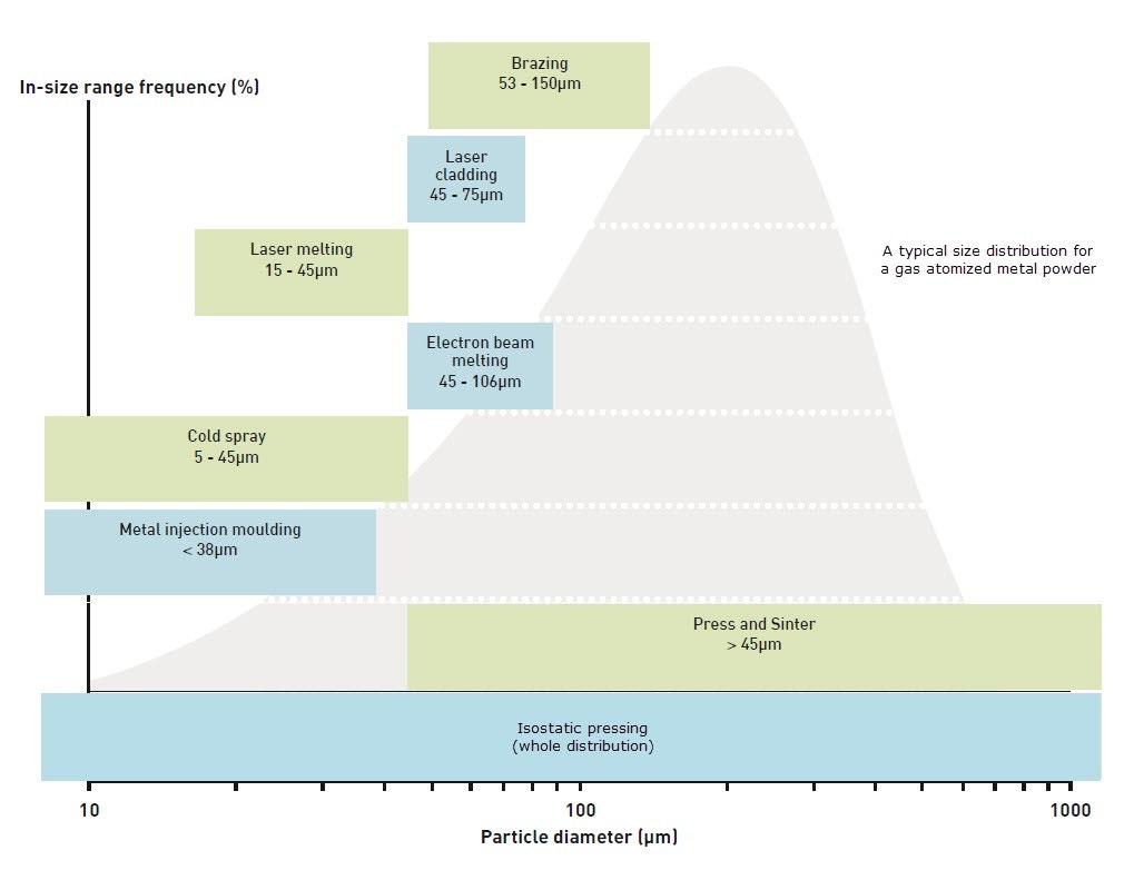
Figure 4: Typical as-atomized particle size distribution of gas-atomized powders, including required size distributions for various advanced powder metallurgy manufacturing technologies.
As stated previously, spherical particles are most suitable for powder bed AM because they have better packing and flowability. Gas-atomized particles are relatively spherical but may have unwanted features such as satellite formation, where small and larger particles fuse or agglomerate during atomization to form irregular shapes. Not only does satellite formation impair flowability and packing, but the satellite particles are so small (usually 1-10 microns) that they can also become an airborne health and safety risk if detached. More spherical particles can be produced by Plasma Atomization or the Plasma Rotating Electrode Process (PREP), but at a higher price [3].
With a measurement range from 0.01 to 3,500 µm, laser diffraction is the particle sizing technology of choice for most AM applications – particularly at smaller size ranges. Laser diffraction systems determine particle size from the resulting light scattering pattern as a collimated laser beam passes through the sample, as shown in Figure 5. Large particles scatter with high intensity at narrow angles relative to the incident beam, while the signal generated by smaller particles is weaker but extends to wider angles. Laser diffraction analyzers calculate the particle size distribution of the sample from the measured angular dependence of the scattered light using an appropriate theory of light scattering, generally the Mie theory.
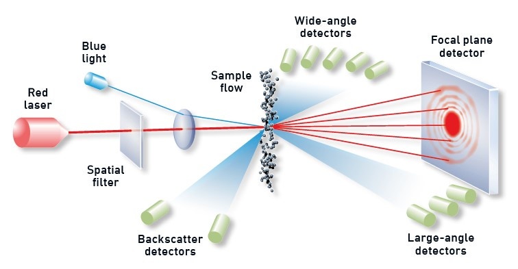
Figure 5: Illustration showing the principle behind a laser diffraction measurement, with diffracted light from dispersed particles picked up by optimally positioned detectors.
Modern laser diffraction systems such as the Mastersizer 3000 are highly automated, to the point of push-button operation, and offer high-throughput analysis with minimal manual input. Besides laboratory-based laser diffraction systems, there are also online process systems, such as Insitec, that deliver real-time particle size monitoring for automated process control. These online process systems can be used either to monitor particle size evolution during atomization, grinding, or spray drying, or at an end-user facility for automated powder handling and recycling [7].
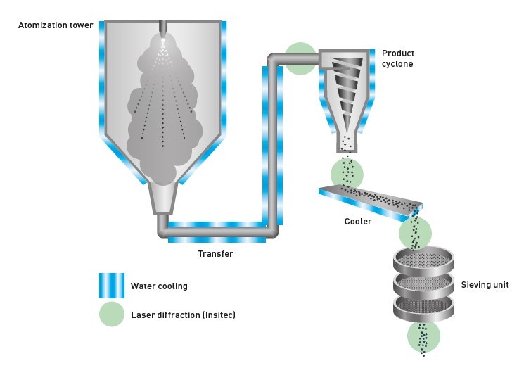
Figure 6: Schematic of a gas-atomization process for manufacturing metal powders, showing the points where laser diffraction can be employed.
Figure 7 shows measurements for four fractions of metal powders, made using both wet and dry dispersion on the Mastersizer 3000. Both wet and dry dispersion are suitable for analyzing metal powders and should give equivalent results if the dispersion procedures are optimized and sampling is comparable. For the <150µm fraction, there is a noticeable discrepancy between the wet and dry measurements. This is likely due either to fine particles adhering to larger particles in the dry state, or a difference in sampling [8].
<150µm 64-150µm
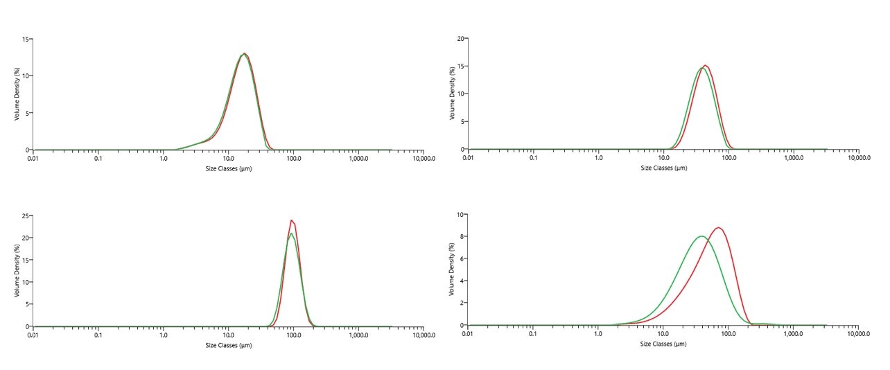
20-64µm < 53µm
Figure 7: Comparisons of wet and dry measurements for each stainless-steel 316L powder sample. In each case, the red trace shows the dry powder spectral density (PSD) and the green trace shows the wet PSD. Each trace shows the average result over five measurements.
Table 1 below shows a comparison between dry dispersion measurements from the Mastersizer 3000 (lab analyzer) and Insitec (on-line analyzer) for four different size fractions of a stainless-steel powder. The Insitec and Mastersizer results are in good agreement for all fractions, with the Insitec results < 2% higher than the Mastersizer results [9].
| < 25 µm | 20 – 64 µm | 64 – 150 µm | < 150 µm | |||||
|---|---|---|---|---|---|---|---|---|
| Mastersizer 3000 | Insitec | Mastersizer 3000 | Insitec | Mastersizer 3000 | Insitec | Mastersizer 3000 | Insitec | |
| d10 | 7.46 | 7.11 | 25.3 | 24.9 | 68.9 | 67 | 16.7 | 16.5 |
| d50 | 15.9 | 16.5 | 42.3 | 44.2 | 94.7 | 94.2 | 54.7 | 56.7 |
| d90 | 27.0 | 27.2 | 68.2 | 70.0 | 131 | 134 | 117 | 122 |
When it comes to characterizing the particles used in metal AM, three main techniques are commonly used: dynamic image analysis, automated static image analysis, and scanning electron microscopy (SEM). The key distinction between these techniques is the number of individual images generated and the resolution of those images [10]:
Dynamic imaging systems, such as the Hydro Insight, can be integrated into your laser diffraction workflow to give particle shape information at the same time as your laser diffraction measurements. Particles suspended in a flowing stream by the laser diffraction dispersion unit flow through the Hydro Insight and are then photographed by a high-resolution digital camera. The images are stored for viewing and converted to a digital format for real-time image analysis and quantification of size and/or shape.
The most significant benefits of this approach are that large numbers of particles can be measured quickly (as with laser diffraction) and that all three particle dimensions are captured, due to the random orientation of the particles. Other benefits include the ability to detect small numbers of oversize particles or contaminants that laser diffraction may miss, and to troubleshoot or optimize laser diffraction methods [11]. Additionally, the Hydro Insight also provides a built-in algorithm for correlating particle size data with sieve analysis. The algorithm measures the bounded rectangular width of irregular particles that would fit through a sieve mesh of the same size and automatically sorts the data into sieve fractions. These measurements tend to correlate better with sieve analysis than equivalent circular areas or spherical diameters reported by laser diffraction, especially when dealing with non-spherical particles [12].
![[Fig 8 Thumbnail images of metal powders, captured by Hydro Insight.jpg] 637629940672274018US.jpg](https://dam.malvernpanalytical.com/ce6332e2-ccea-4e8d-9985-ada001613215/637629940672274018US_Original%20file.jpg)
Figure 8: Thumbnail images of metal powders, captured by Hydro Insight.
| Aperture size (µm) | ECA diameter % | BR width % | Differences |
|---|---|---|---|
| <20 | 0.02 | 0.543 | -0.523 |
| 20 | 2.017 | 6.378 | -4.361 |
| 25 | 16.818 | 24.692 | -7.874 |
| 32 | 22.987 | 26.327 | -3.34 |
| 38 | 23.495 | 15.666 | 7.829 |
| 45 | 9.817 | 2.496 | 7.321 |
| 53 | 3.913 | 3.071 | 0.842 |
| 63 | 3.265 | 3.497 | -0.232 |
| 73 | 4.254 | 4.585 | -0331 |
| 90 | 2.257 | 1.825 | 0.432 |
| 103 | 2.747 | 2.450 | 0.297 |
| 125 | 4.217 | 3.688 | 0.529 |
| 150 | 2.280 | 2.772 | -0.492 |
| 180 | 1.913 | 2.011 | -0.098 |
Suitable for particles from approximately 0.5 µm to > 1 mm, static imaging systems such as Morphologi 4 capture individual images of tens of thousands of particles. From these images, multiple size and shape parameters can be calculated. Unlike in dynamic imaging, the sample is dispersed on a substrate and remains effectively static. The substrate is then moved relative to the microscope optics, situated above the sample, using a motorized stage. The sample is illuminated from either below the stage (diascopic) or above it (episcopic), depending on the image requirements. The captured images are processed for size and shape analysis. Figure 9 illustrates this workflow.
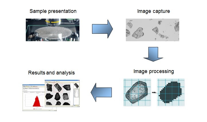
Figure 9: Illustration showing the general workflow for an automated imaging measurement.
Because the distance between the microscope and substrate is well controlled, all the particles remain in focus during the measurement, so the resulting images are of higher quality than with a dynamic approach. Static imaging also reliably captures the two largest particle dimensions of irregular particles, since they take a preferred orientation on the substrate. Furthermore, because the position of each particle is recorded, particles of interest can be revisited with higher magnification for a more detailed study.
The Morphologi 4 provides 20 different shape parameters, including circularity, elongation, convexity, and solidity. It can also support customized classifications to examine features such as satelliting. Figure 10 shows several metal powder images taken with the Morphologi 4. The instrument has automatically classified and grouped these images based on their shape, taking into account parameters such as sphericality, elongation, and the presence of satellites [13].
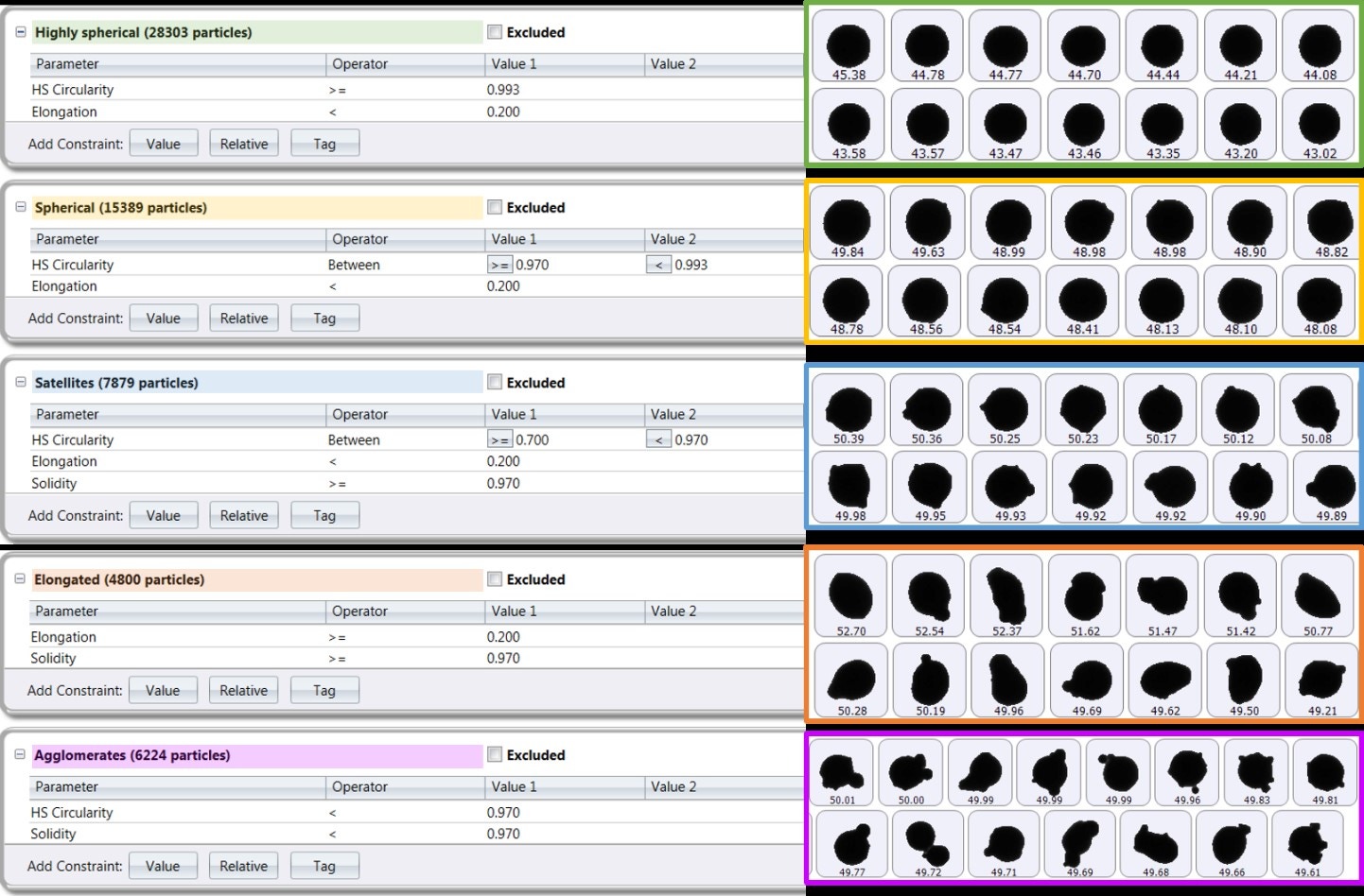
Figure 10: Particle classifications for an AM metal powder with corresponding particle images.
The size and shape of metal powder particles affect powder bed packing and flowability. In turn, these features impact the build quality and final properties of components manufactured using AM. As such, understanding and optimizing particle size and shape is critical to the success of powder-bed AM. Laser diffraction and automated image analysis are complementary tools that can be used to characterize and optimize metal powders for a range of powder-bed AM processes.